David Hudson posted a comment on his experience with the Omni faceting machine’s 45 degree angle adapter yesterday. His comment can be found here:
https://www.omnifaceter.net/another-omni-owners-spindle-and-platen/#comment-23
He forwarded me some photos to back up his text. I’ve copied his comments here as well as posted his photos. As you can see, his nearly-completed stone was totally destroyed when the 45 degree angle adapter literally fell apart.
By hacklebox44 on Mar 11, 2009
Well, the latest fall apart stunt of my OMNIe has just cost me a very nice stone. Yesterday I was cutting a very nice piece of Tanzanian Sunstone. I had the stone complete except for the table, using the 45 degree fixture as I often do I noticed the table wasn’t cutting like it should. All of a sudden the head of the 45 degree fixture fell off hitting the spinning lap and ending up on the floor. I found my stone broken and completely ruined.
Upon checking the fixture to see what the heck had just happened I found the fixture was simply glued together and after near three years of use the glue had dissolved and the fixture fell apart. I talked with two other OMNIe owners that I know and they have had the same problem at one time or the other with their machines.I must say that quality machining and quality workmanship surely shouldn’t include glueing machined pieces together. Again the quality of this machine has reached another new LOW FOR ME, and I am headed to a local show this weekend to check into the possibility of buying different faceting machine, I am tired of trying to keep this piece of junk running.
Of course this is my opionion and should be viewed as such.
David Hudson

45 Degree Angle Adapter from David's Omni Faceting Machine

Broken 45 Degree Angle Adapter from David's Omni Faceting Machine
And here are the unfortunate consequences of David’s 45 Degree Angle Adapter falling apart. If you can imagine the heavy head of the adapter along with a dop and stone attached suddenly falling off the machine and being flung around the lap and across the room, you can understand why the stone ended up the way it has.
My 45 degree adapter with a standard Omni dop weighs an impressive 85 grams. Subtract about 20 grams for the shaft of the adapter and you’ve got 65 grams – more than 2 oz – of brass and stone flying about the room. I expect anyone being hit by that would not be very happy, and being hit in the head or fingers would result in injuries.

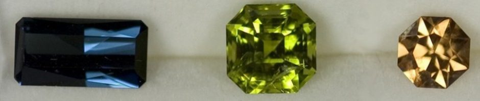
The Tanzanian Sunstone destroyed when the 45 Degree Adapter fell apart
Finally, here’s a close-up of the 45 degree table adapter from my own Omni faceting machine. Note the black around the joint where the shaft joins the head. From my early emails with Charlie at Jersey Instruments, he indicated this is pitch used to hold the head in place. Not a press-fit or threaded attachment for such a critical part, but simple pitch.
This part was out of alignment when I first received my Omni, and was among the first parts to be returned for servicing. The “servicing” – which apparently consisted of heating and twisting the dop to the correct orientation – took over 3 weeks. Because I’ve had more pressing issues with my Omni faceting machine, this bit of crappy quality hadn’t made it into the site yet.
As you might guess, my next modification is to either have my table adapter silver-soldered like Dave, or have a new one with a better design manufactured. I’m leaning towards the latter.

My Omni Faceting Machine 45 Degree Table Adapter - note the pitch along the joint

Another View - My Omni 45 Degree Table Adapter with pitch holding it together


